Download Entity Relationship (ER) Diagram
Subscribe our YouTube channel for latest project videos and tutorials Click Here
An Entity Relationship Diagram is a graphical representation of entities and their relationships to each other. An Entity Relationship Diagram is a type of flowchart that illustrates how “entities” like people, objects or concepts relate to each other within a system. ER Diagrams are mostly used to design or debug relational databases in the fields of computer science, business information systems, education and research. ER diagrams are related to data structure diagrams (DSDs), which focus on the relationships of elements within entities instead of relationships between entities themselves.
Here we are developing all type of er diagrams online for projects. Our website Freeprojectz.com provide er diagram and report solution for the final year engineering students. Here student can easily download er diagram online.
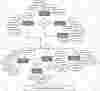
Helpdesk Ticketing System ER Diagram
This ER (Entity Relationship) Diagram represents the model of Helpdesk Ticketing System Entity. The entity-relationship diagram of Helpdesk Ticketing System shows all the visual instrument of database tables and the relations between Support, Client, Ticket, Track etc. It used structure data and to define the relationships between structured data groups of Helpdesk Ticketing System functionalities. The main entities of the Helpdesk Ticketing System are Ticket, Support, Helpdesk, Client, Issue and Track.
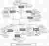
Cargo Management System ER Diagram
This ER (Entity Relationship) Diagram represents the model of Cargo Management System Entity. The entity-relationship diagram of Cargo Management System shows all the visual instrument of database tables and the relations between Cargo, Billing, Customer, Payment etc. It used structure data and to define the relationships between structured data groups of Cargo Management System functionalities. The main entities of the Cargo Management System are Customer, Cargo, Transaction, Billing, Enquiry and Payment.
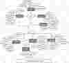
Inventory System ER Diagram
This ER (Entity Relationship) Diagram represents the model of Inventory System Entity. The entity-relationship diagram of Inventory System shows all the visual instrument of database tables and the relations between Category, Warning, Goods, Manager etc. It used structure data and to define the relationships between structured data groups of Inventory System functionalities. The main entities of the Inventory System are Goods, Category, Worker, Warning, Expiry and Manager.
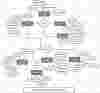
Banking Management System ER Diagram
This ER (Entity Relationship) Diagram represents the model of Banking Management System Entity. The entity-relationship diagram of Banking Management System shows all the visual instrument of database tables and the relations between Employees, Fixed Deposit, Customer, Current Account etc. It used structure data and to define the relationships between structured data groups of Banking Management System functionalities. The main entities of the Banking Management System are Customer, Employees, Accounts, Fixed Deposit, Saving Account and Current Account.
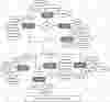
Export Order Tracking System ER Diagram
This ER (Entity Relationship) Diagram represents the model of Export Order Tracking System Entity. The entity-relationship diagram of Export Order Tracking System shows all the visual instrument of database tables and the relations between Products, Payments, Exports, Inventory etc. It used structure data and to define the relationships between structured data groups of Export Order Tracking System functionalities. The main entities of the Export Order Tracking System are Exports, Products, Sales, Payments, Stock and Inventory.
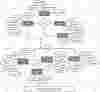
Car Parking System ER Diagram
This ER (Entity Relationship) Diagram represents the model of Car Parking System Entity. The entity-relationship diagram of Car Parking System shows all the visual instrument of database tables and the relations between Parking, Parking Space, Car, Car Owner etc. It used structure data and to define the relationships between structured data groups of Car Parking System functionalities. The main entities of the Car Parking System are Car, Parking, Parking Slots, Parking Space, Parking Fees and Car Owner.
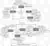
E-Governace System ER Diagram
This ER (Entity Relationship) Diagram represents the model of E-Governace System Entity. The entity-relationship diagram of E-Governace System shows all the visual instrument of database tables and the relations between Petition, Customer, Bill, Government Services etc. It used structure data and to define the relationships between structured data groups of E-Governace System functionalities. The main entities of the E-Governace System are Bill, Petition, Payment, Customer, Exchange of Information and Government Services.
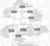
Medical Diagnostic System ER Diagram
This ER (Entity Relationship) Diagram represents the model of Medical Diagnostic System Entity. The entity-relationship diagram of Medical Diagnostic System shows all the visual instrument of database tables and the relations between Tests, Doctors, Medical Reports, Employees etc. It used structure data and to define the relationships between structured data groups of Medical Diagnostic System functionalities. The main entities of the Medical Diagnostic System are Medical Reports, Tests, Diagnosis, Doctors, Charges and Employees.
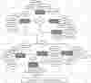
Crime File Management System ER Diagram
This ER (Entity Relationship) Diagram represents the model of Crime File Management System Entity. The entity-relationship diagram of Crime File Management System shows all the visual instrument of database tables and the relations between Complaints, Charge Sheet, Crime, Criminals etc. It used structure data and to define the relationships between structured data groups of Crime File Management System functionalities. The main entities of the Crime File Management System are Crime, Complaints, FIR, Charge Sheet, Presioner and Criminals.

Internet Monitoring System ER Diagram
This ER (Entity Relationship) Diagram represents the model of Internet Monitoring System Entity. The entity-relationship diagram of Internet Monitoring System shows all the visual instrument of database tables and the relations between User, Password, Customer, Login etc. It used structure data and to define the relationships between structured data groups of Internet Monitoring System functionalities. The main entities of the Internet Monitoring System are Customer, User, User Code, Password, Report and Login.